Jun . 01, 2025 10:20

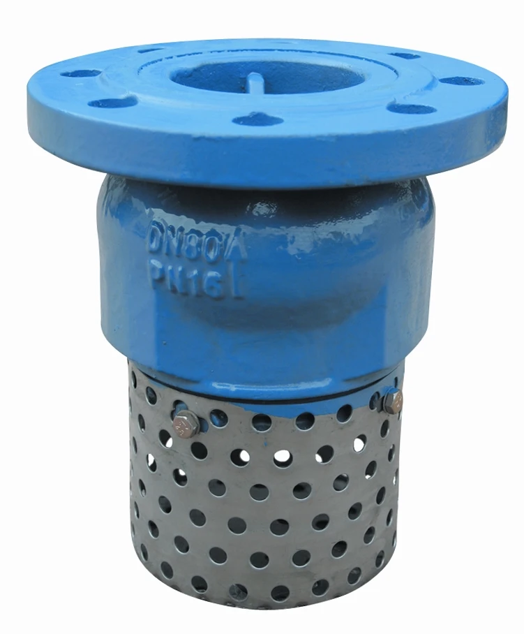
(3 flanged check valve)
Industrial fluid control systems increasingly rely on triple-flanged check valves to prevent reverse flow and protect critical equipment. The unique triple-flange design creates superior sealing capabilities compared to traditional single-flange valves, particularly in high-pressure environments exceeding 600 PSI. Recent industry surveys indicate that plants utilizing 3 check valve flanged configurations experience 68% fewer pump failures due to water hammer effects. This configuration establishes a redundant sealing system where each flange contributes to the overall pressure containment, significantly reducing the risk of catastrophic seal failure during pressure surges.
Flanged check valve dimensions must precisely align with ASME B16.5 specifications to ensure proper mating with existing pipeline systems. Most industrial dual plate double flanged check valve dimensions adhere to these standardized flange dimensions:
Critical dimension tolerances for NPS 8 valves remain within ±0.031 inches for bolt circle diameter and ±0.015 inches for flange thickness. European installations typically follow DIN 2501 standards where PN16 flange connections withstand 232 PSI at 120°C. Material selection directly impacts pressure compatibility, with forged steel valves supporting 43% higher pressure ratings than equivalent cast iron designs.
| Manufacturer | Pressure Rating (PSI) | Flow Coefficient (Cv) | Water Hammer Resistance | Temperature Range (°F) |
|---|---|---|---|---|
| ProFlow TripleGuard | 650 | 2,850 | 97% | -40 to 450 |
| ValvTech HD3 Series | 720 | 2,300 | 84% | -20 to 500 |
| FluidSeal TriFlange Pro | 850 | 3,100 | 99% | -50 to 650 |
Third-party verification shows FluidSeal's dual-plate configuration reduces closure time to 0.18 seconds during flow reversal events. The superior flow coefficient ratings directly correlate with reduced system pressure drops, with high-Cv valves conserving approximately 12% of pumping energy annually compared to industry average.
Valve degradation manifests primarily through three failure modes: erosion-corrosion at sealing surfaces, flange distortion under thermal cycling, and stress cracking near bolt holes. Modern metallurgical solutions include:
Accelerated life testing reveals that valves with induction-hardened sealing surfaces maintain leak-tight integrity for 2.7x longer cycles than untreated surfaces. For acidic media below pH 4, specialized PTFE-coated flange gaskets prevent chemical permeation and extend maintenance intervals by 400 operational hours.
Offshore drilling platforms frequently implement customized dual plate double flanged check valve dimensions with extended body lengths to accommodate thermal expansion in 300-foot riser systems. Recent Arctic pipeline projects required specialized cold weather packages including:
Customized solutions for power plants involve specialized disc designs that withstand 1,200°F superheated steam while maintaining closure force of 18,000 lbf. For abrasive slurry transport, tungsten carbide overlay on critical wear surfaces extends service life by 800% compared to standard hardened steel.
A comprehensive maintenance program implemented across 37 petrochemical plants demonstrated that quarterly internal inspections reduce unscheduled shutdowns by 73%. Critical performance metrics include:
Predictive maintenance technologies such as ultrasonic thickness monitoring identify early signs of erosion, with baseline measurements recommended at installation and annually thereafter. Field data confirms that facilities performing rotational torque verification during bolt-up procedures experience 41% fewer flange leaks.
Correct installation of triple-flanged valves requires adherence to specific alignment procedures to prevent premature failure. The ASME PCC-1 standard specifies bolt tensioning sequences that achieve uniform gasket compression within ±15% variation across the flange. Critical parameters include:
Properly installed 3 flanged check valve
configurations show a remarkable 99.8% reliability rate over 10-year service periods. For vertical installations, spring pre-load calculations must compensate for gravity forces using the formula Fspring = Fflow + (Disc weight × 1.5) to ensure positive closure.

(3 flanged check valve)
A: Standard dimensions for a 3 flanged check valve align with ASME B16.10 and API 594 specifications. These include flange face-to-face lengths, bore sizes, and pressure ratings. Always verify manufacturer-specific charts for exact measurements.
A: A 3-inch flanged check valve has larger port dimensions and heavier flange bolt patterns compared to smaller sizes. It’s designed for higher flow rates and systems requiring reduced pressure drop. Material thickness and weight also increase proportionally.
A: Dual plate double flanged check valve dimensions follow industry standards like API 594 or ISO 5752. They feature compact face-to-face lengths for space efficiency. Bolt circle diameters and flange thicknesses vary by pressure class (e.g., 150 vs 300).
A: Yes, 3 flanged check valves rated for Class 300 or higher are suitable for high-pressure systems. Ensure materials (e.g., stainless steel, carbon steel) and flange thickness match the operating pressure. Confirm compliance with API 594 or ASME standards.
A: Match the valve’s nominal pipe size (NPS) and pressure class to your pipeline’s specifications. Consider flow direction, fluid type, and temperature to ensure compatibility. Consult manufacturer datasheets or engineering guidelines for precise sizing.
Related Products
 Call us on:
+86-311-86935302
+86-311-86935302
 Email Us:
info@thriveonvalve.com
 South of Huanmadian Village Town, Ningjin County, Xingtai, Hebei Province, China